RPi-Powered Robot Arm
Objective
The objective of this project was to demonstrate the ability to control a robotic arm using the Raspberry Pi. Specific goals included deriving the kinematics formulation to map servo angles to real-world end effector positions in space and being able to control the robotic arm to pick up objects in the final demo.
Introduction
Through this project, we worked on every aspect of controlling a robotic manipulator, from mechanically and electrically integrating the arm to deriving the kinematics formulation and implementing user control. First, we laser cut parts based on an open-source robotic arm design, then assembled the arm. Next, we wired the arm such that each servo could receive PWM from the RPi and tested the functionality of the servos on and off the arm. After deriving kinematic equations for the arm, we measured the effect of servo speeds on key angles in the formulation and mapped combinations of servo values to real-world coordinates. Finally, we used our knowledge of the arm’s inverse kinematics to repeatably pick up and drop off a Sharpie at various locations.
Demonstration Video
Design & Testing
Mechanical Integration
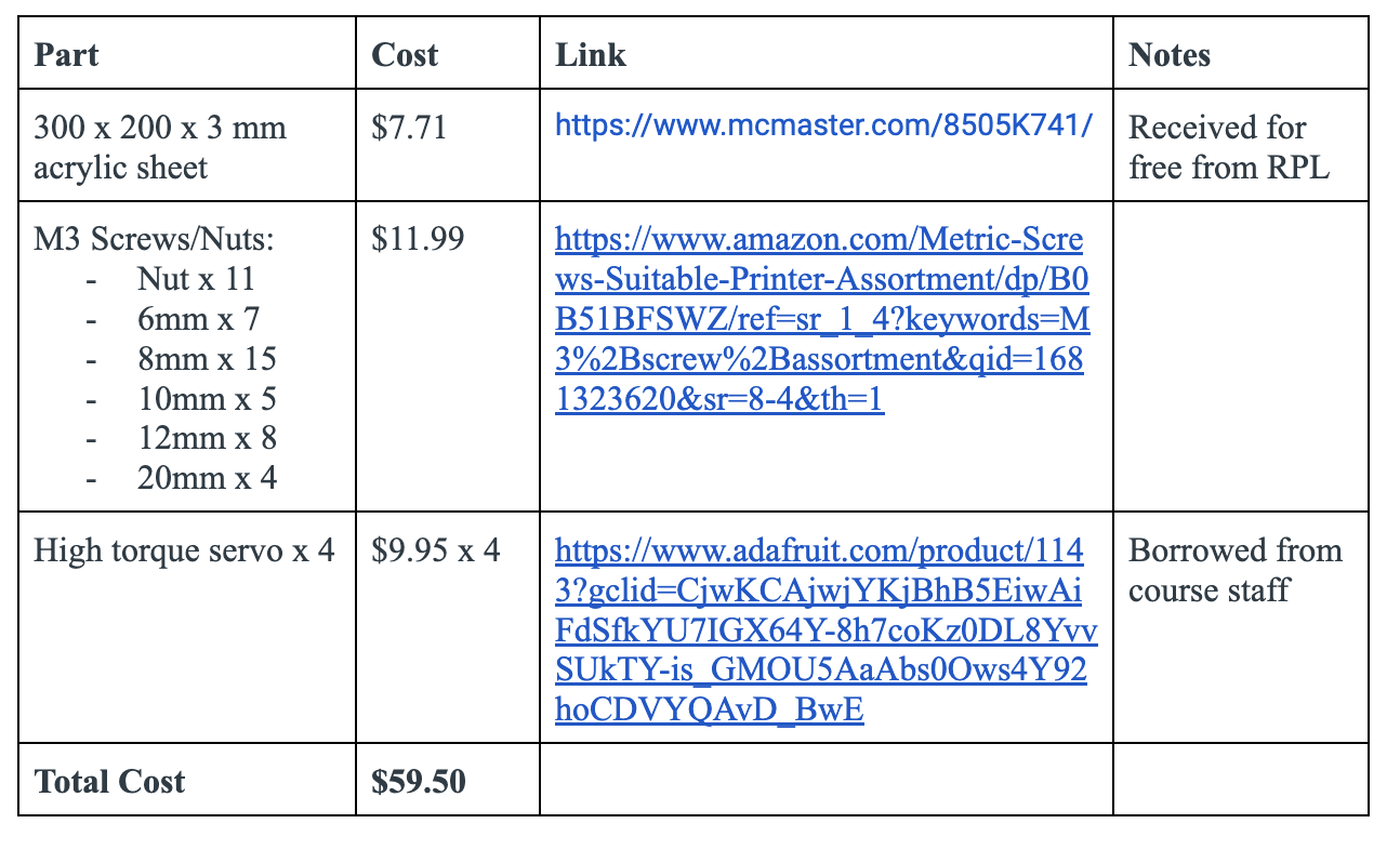
We built a MeArm v1.0 as our robotic arm for the project. The MeArm is an open-source arm that can be laser-cut from a single 300 x 200 x 3 mm acrylic sheet and assembled without any power tools. We identified this arm based on suggestion by the course staff as well as from looking at the CAD model [1]. We then laser cut the arm using DXF files found on GitHub [2] through the Rapid Prototyping Laboratory, then purchased screws as listed on an assembly guide [3], found servos, and referenced the CAD model to assemble the arm.
Because the arm was laser cut, the holes on the parts had no threads, and the screws had to be driven into the parts by hand. This caused some challenges with alignment, and we had some questions about how tightly the screws should be fastened. However, we did not notice alignment or friction issues with the final assembly.
We found that the weight of the robot both caused the base of the assembly to tip when sitting flat on a table and caused the arm as a whole to tip on its servo base. We also encountered challenges with getting the servos to remain consistently aligned with mechanical parts of the robot, as the servo horns were press fit into holes on the laser-cut parts, and this friction could easily be overcome by the high-torque servos. In the end, we hot glued the servo horns in place to prevent misalignment, but issues with the alignment of and tipping relative to the base servo persisted throughout the project due to the weight of the entire robot resting on the servo.
Because the robot was capable of reaching so far below its base, we extended the reach envelope of the robot by elevating the base on a cardboard box.
Electrical Integration
The electrical curve in this particular project was relatively minimal. The primary challenge involved dealing with the limited availability of hardware GPIO pins. With only 2 pairs readily available on the RPi, 2 of the servos were relegated to regular GPIO pins. Though there were 4 gpio pins that could operate as hardware gpio pins, each pair was constrained to the same PWM signal, leading to minimal differential flexibility. Ultimately, a design choice was made to make the link motors dependent on the hardware_gpio servos while the base and gripper servos were driven by regular gpio pins.
Another electrical design choice involved choosing to operate the servos using the power supply to allow maintaining a constant voltage and avoid unintentional voltage drops from fluctuating current. The current was particularly more volatile in the project due to the uneven weight distribution and stress on the servo’s motors when extending and retracting the arm. The link servos would frequently jerk back and forth when powered through a battery since the battery failed to maintain a constant 5.5 volts to all the servos.
Servo Testing
Initial testing involved first understanding the realistic range of motion of the servo. The motor’s control is similar to that of the servo. They both function under the influence of PWM. The motor utilizes the PWM to determine its current speed with the duty cycle controlling the magnitude of the motor’s rotation. However, the servo utilizes the PWM signal as a time-based indicator. A full duty cycle on the PWM signal signifies a full rotation of the servo (180 degrees). This time-based position control based on the width of the pwm signal provides an extremely nuanced control of the position.
The time scale supported by the RPi through its hardware_gpio pulse method operated on a microseconds time scale, with each reasonable increment (10 or more) providing a noticeable update in the servo’s position. While internally changes under 10 microseconds are registered, the rotational friction of the base and the axle could only be overcome in the increment registered above. To combat the servo’s abrupt movement to the desired position, a more brute-force method of moving to every position in the middle in gaps of extremely minimal time intervals was adopted.
Initial Kinematics Formulation

The initial kinematics formulation was governed by two main assumptions: the links were independent and the servo values could linearly scale to angle values. The first assumption in this case was important when trying to develop the inverse kinematics formulation for angle between both links (here this corresponds to theta 2). By utilizing the law of cosines, the angles associated with link 1 and link 2 are found as detailed above. A major constraint during this inverse kinematics formulation involved limiting the arm’s lowest y-coordinate to be the base of the robot despite the robot arm having the ability to go below the limit mechanically. This made keeping the angular directions consistent, easier to track, and computationally simpler.
Servo Position Mapping
Based on this initial kinematics formulation, we sought to map the speeds of the servo on GPIO pin 12 (“Servo 12”) and the servo on GPIO pin 6 (“Servo 6”) to the angles theta 1 and theta 2, respectively. However, because we noticed that theta 2 was not independent of theta 1, we began to define new key angles with which to map servo values.
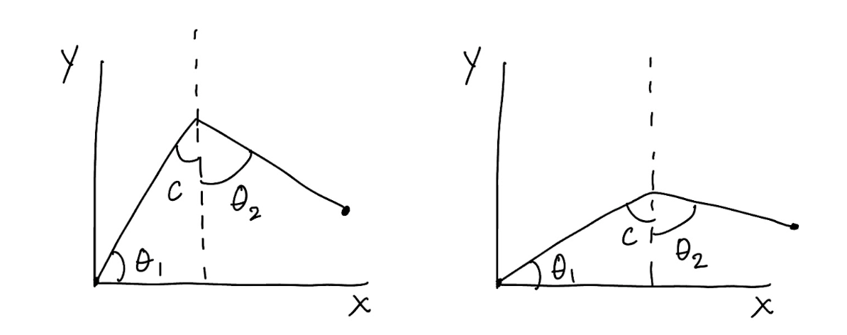
While theta 1 remained the same, the angle between the two linkages, initially called theta 2, was renamed to beta and split up into two new angles. The first of these angles, c, was an angle with respect to the vertical and represented the contribution of changes in theta 1 to the angle between the two linkages. The next angle, theta 2, was defined to be completely independent of theta 1 and represent only the movement of Servo 6.
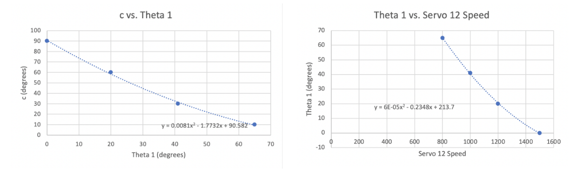
Setting the two servos to their electrical and mechanical limits as well as values in between, we then used a protractor to measure these angles and their corresponding servo values. By setting Servo 6 such that the second linkage was completely vertical, we were able to measure the angle c directly, then compare c to theta 1 and theta 1 to Servo 12 speeds, as shown in the plots below.
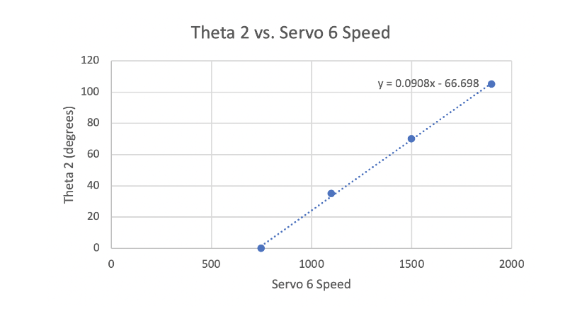
We then varied Servo 6’s speed with a known c value of 10 degrees in order to determine the value of theta 2 alone from protractor measurements between the two linkage
As shown in these plots, both tests that involved measuring theta 1 resulted in data that appeared to be best fit with a parabolic curve. This curve of best fit diverged from our intuition that c, theta 1, and the associated servo speed would be linearly related.
After additional thought, we determined that c and theta 1 would sum to 90 degrees, as the former was an angle with respect to the vertical, and the latter with respect to the horizontal. We also determined that non-linearities stemmed from measurement error, both due to the imprecision of the protractor and because, as mentioned in Section 1 (Mechanical Integration), the arm itself had a tendency to tilt relative to its base, making measurements with respect to the vertical both variable based on the arm’s position and difficult to measure.
Because real-life non-linearity was difficult to map because of the additional factor of measurement imprecision, we decided to base our code on the theoretical relationships between angles and servo speeds. Using the measurements for angles c and theta 2, which we anticipated would be more accurate than the theta 1 measurements, at the retraction and extension limits of the servos, we found linear relationships between the servo speeds and angles. These calculations were verified through a script of helper methods, dynamics_angles_test.py (Code Appendix). Inverse kinematics were calculated using the results of a forward kinematics calculation, ensuring the input and output angles matched. Then, the x and y limits of the robot’s reach envelope were generated from the servo limits.
Final Kinematics Formulation
The final kinematics formulation was based on the modified angle definitions shown in the diagram in Section 5, included again below for reference:
The final kinematics formulation was based on the modified angle definitions shown in the diagram in Section 5, included again below for reference:
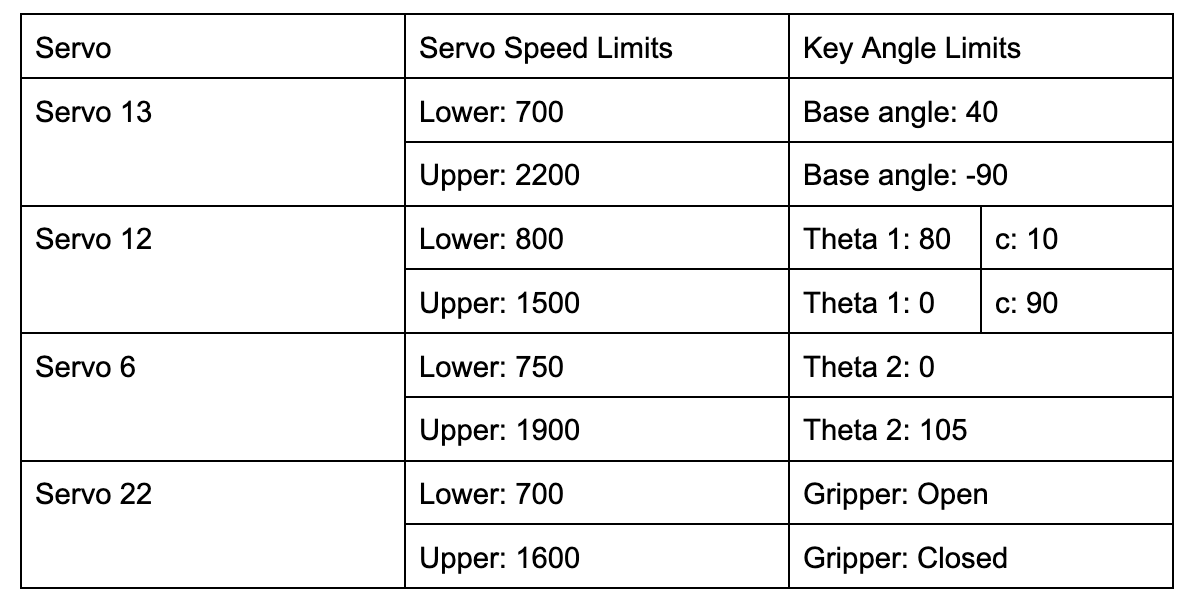
Different positioning of the mechanical parts relative to the servo shafts would result in different relationships between servo speeds and key angles. To visualize the above limits, a program called arm_test.py was written to sweep through key angles and test extension limits of the arm.
Initial Testing
The primary focus of the initial tests involved making sure the arm’s dynamics was indeed properly corrected to reach any reasonable point in space. To test this, the arm’s task was focused to only pick up the sharpie from smallest height.
The first step in this task was to determine the x and y position of the center of the pen. Through a few rudimentary measurements, the position of the pen was then converted to mm to feed into the arm dynamics. Experimentally, there were limited obstacles in getting the right servo values for the extension. The primary obstacle was determine the base angle to utilize to turn to the desired position. Ultimately, the servo’s value for the correct position was determined experimentally, though there still remained a fair bit of variability.
Final Program
For the final program, the functionality developed during initial testing was expanded upon. Using the existing retraction sequence, an extension sequence was developed to manage collisions between the robot and its surroundings. Instead of programming the robot to go directly to the specified point in space, this new script had the robot reach up above its final position, extend out, and finally move down to its final destination. This prevented the arm from colliding with a container when extending out. Additionally, instead of moving directly between points, the robot retracted after each specified point to allow it to repeat its clearance sequence before the next position.
Additionally, it was found during this phase of testing that a method used to calculate a slow trajectory between the arm’s current and final positions, get_servo_pulsewidth, required the servos to be “initialized,” or commanded to, before calling the method. While this issue could be resolved by setting the arm to its retracted position at the start of the program, moving quickly from an arbitrary arm position to the retracted position could cause servo misalignment from the rapid and jerky movement. To prevent this from happening, a quit function was developed to release the object in the robot’s grasp and safely and slowly bring the arm back to its initial position when ending the run of a program.
In the end, the program successfully allowed inverse kinematics to be calculated for any point in space within the robot’s reach envelope. The locations of the three containers were not hard coded; instead, they were recorded and provided as user inputs to the kinematics calculation. The locations of the three containers relative were as follows:
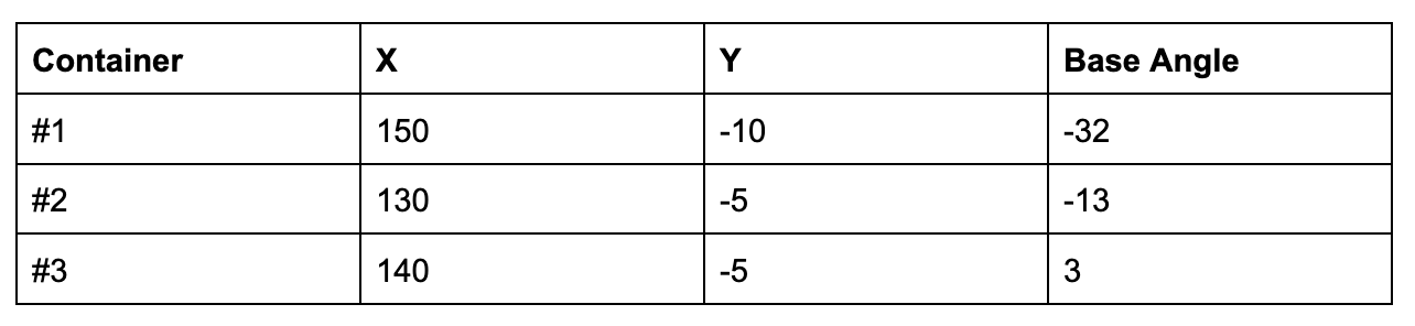
We found that the sharpie was more easily able to clear the containers when the dropoff Y coordinate was about 10 millimeters higher than the pickup location. For example, for container #1, Y would be set to -10 millimeters when picking up the sharpie but 0 millimeters when dropping off the sharpie.
Results
Through extensive testing, we were eventually able to repeatably pick and place the sharpie in three specified locations by entering known coordinates in space into the user interface. We were happy to see that the arm was able to pick up an object as heavy and long as a sharpie despite its small size. We expected the payload to be much smaller, especially when we first encountered issues with the servos jerking back and forth, which we initially took to mean the servos could not handle the gravitational torque from the arm at full extension. However, the high-torque servos worked well for this application, and we believe the arm could handle heavier objects at higher extension.
We also accomplished our goal of implementing inverse kinematics and a user interface through which any point in space within the robot’s reach could be commanded to. Though the initial goal of the project was to map screen coordinates on the piTFT to real-world coordinates to enable intuitive control of the arm, the project narrowed in scope to entering coordinates in a terminal but broadened in scope by including a larger range of reachable coordinates in space.
While we did not have time to implement every goal we initially hoped to accomplish, we were able to not only demonstrate a consistent set of actions and the functionality of our calculations but fully understand the limitations and variability associated with the arm through our testing. The only issue that remained at the end of the project was the servos’ inability to overcome the arm’s weight and frictional forces for small changes in servo angles, but we worked around this issue by having the arm between more drastically different points in space.
Conclusion
Through this project, we were able to demonstrate control of the arm for a wide range of points in space, both near the robot and far away. We also were able to consistently pick up and drop off a sharpie, despite variability in the sharpie’s position and the high degree of accuracy necessary for object drop off. While issues with variable servo accuracy remained, we were able to characterize the arm’s reach envelope, identify the locations of the targets, and understand the limitations of the hardware with which we were working.
Future Work
Three key aspects of future work for this project include accomplishing our initial goal of intuitive user control, solving servo accuracy issues we encountered, and implementing sensing or autonomy.
In our initial project proposal, we hoped to create a graphical user interface on the piTFT through which a user could control the arm. This would involve the user tapping coordinates on the screen that would then translate to real-world coordinates, as well as using a slider to change either the base angle of the robot or the height of the end effector. We did not have time to implement this, but it would be an interesting extension of this project.
Although we used high-torque servos, they still struggled to overcome frictional forces or the weight of the arm in certain cases—mainly in the case of the base servo, which had to move the weight of the entire arm, sometimes by very small changes in servo angle. This caused a lot of variability in the real position of the arm, as it did not always map linearly to the servo position. In the future, the servos could be replaced with higher torque motors or used in conjunction with external sensors and a controller to have a better understanding of the real position of the arm.
Finally, an interesting extension of the project would be using a camera as well as sensors and a controller to autonomously detect and pick up objects in the robot’s surroundings. While this would not be possible with the current hardware due to the servos’ inability to change by very small angles and therefore converge on a location in space according to inputs from a controller, upgrading the hardware and adding a camera would enable accomplishing this goal.
Individual Contributions
Nikki Hart primarily focused on extending the initial tests and dynamic formulations to cover the wider range of cases. This involved determining various feasible positions and better constraining the project as necessary. Nikki also focused on developing a more streamline codebase to better demonstrate the capabilities of the robot arm during the demo.
Nikhil Pillai focused on the initial portions of each stage which involved developing the first set of inverse kinematics formulations and servo tests. The major challenge involved tuning and testing the dynamics to pick up a single sharpie from the smallest height to provide a reasonable model for picking additional pens.

Nikhil
Nikki Hart
Code
Budget
Budget